
Direct answer
An intrinsically safe (I.S.) detection circuit on a Hochiki ESP addressable system has four parts: certified I.S. devices in the hazardous area (SOC-E-IS or DCD-1E-IS detectors on YBN-R/4IS bases, CCP-E-IS call points), a certified barrier (Hochiki Europe technical support recommends a Pepperl+Fuchs KFD0 galvanic isolator for both detection and sounder circuits), I.S.-compatible interface modules in the safe area (CHQ-DZM(SCI)-IS for detection, CHQ-ISM driven by a sounder controller for sounders or beacons) and a 24 V DC auxiliary supply. Each detection zone takes up to 20 detectors, and each CHQ-ISM barrier channel takes only one I.S. sounder or one I.S. beacon.
Applies to
- Products / Models: CHQ-DZM(SCI)-IS and CHQ-DZM/DIN(SCI)-IS I.S.-compatible dual zone monitors; CHQ-ISM and CHQ-ISM/DIN I.S.-compatible sounder interface modules; CHQ-DSC2(SCI) sounder controller (written CHQ-DSC in the CHQ-ISM instructions); SOC-E-IS and DCD-1E-IS detectors with the YBN-R/4IS base; CCP-E-IS call points; Pepperl+Fuchs KFD0-CS-Ex2.51P and KFD0-CS-Ex1.51P galvanic isolators; SMB-2 and SMB-3 DIN module enclosures
- Firmware / Version: Not applicable
- Region: UK / Europe
- Standards: CHQ-DZM(SCI)-IS — BS EN 54-17, BS EN 54-18; CHQ-ISM — BS EN 54-18; SOC-E-IS — BS EN 54-7; I.S. system drawings — BS EN 60079-11:2012; installation in the hazardous area — BS EN 60079-14
How the circuit is arranged
The control panel loop runs to the interface modules, the modules feed the barrier, and only the barrier output enters the hazardous area. The CHQ-DZM(SCI)-IS, the CHQ-ISM and the barrier are not themselves intrinsically safe and must all be installed in the safe area.
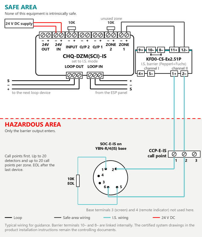
- Detection: loop, then CHQ-DZM(SCI)-IS (one loop address, two zones), then one barrier channel per zone, then call points and detectors in the hazardous area with the end-of-line resistor after the last device.
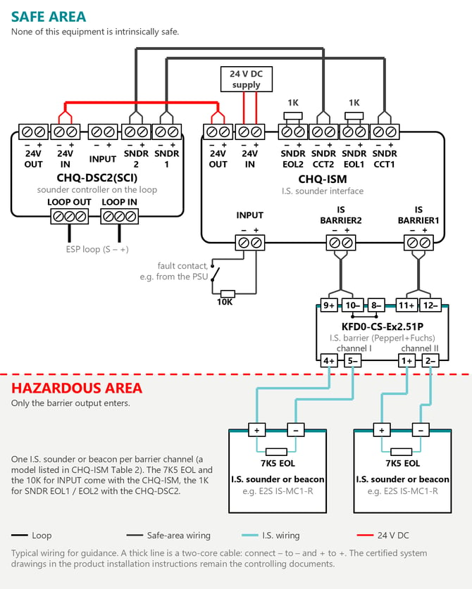
- Sounders and beacons: loop, then a sounder controller such as the CHQ-DSC2(SCI) (or a conventional sounder output), then CHQ-ISM, then one barrier channel per I.S. sounder or beacon in the hazardous area.
- Power: both the CHQ-DZM(SCI)-IS and the CHQ-ISM need an external 24 V DC supply on the safe-area side, in addition to the loop.
The two figures below show typical wiring as a guide. The certified system drawings in the product installation instructions remain the controlling documents.
In the typical detection wiring below, ZONE 1 of the CHQ-DZM(SCI)-IS connects to terminals 11+ and 12- of a KFD0-CS-Ex2.51P (barrier channel II), and the hazardous-area circuit leaves from terminals 1+ and 2-. Every terminal block on the module is marked - then + on the product label. The INPUT terminals and an unused zone are each terminated with a 10 kΩ end-of-line resistor supplied with the module.
In the typical sounder wiring below, sounder outputs SNDR 1 and SNDR 2 of the CHQ-DSC2(SCI) connect to SNDR CCT1 and SNDR CCT2 of the CHQ-ISM, and the 1 kΩ end-of-line resistors supplied with the CHQ-DSC2(SCI) are fitted across SNDR EOL1 and SNDR EOL2 on the CHQ-ISM. The 24 V supply goes to 24V IN on the CHQ-ISM, and its 24V OUT feeds 24V IN on the CHQ-DSC2(SCI). IS BARRIER1 connects to terminals 11+ and 12-, and IS BARRIER2 to terminals 9+ and 10-, of a KFD0-CS-Ex2.51P, and each channel (1+ and 2-, or 4+ and 5-) feeds one I.S. sounder or beacon with a 7K5 end-of-line resistor at the device.
Steps
- Confirm the area classification and choose certified devices. The hazardous area classification for the site determines which equipment may be installed there. The SOC-E-IS and DCD-1E-IS are certified II 1 G Ex ia IIC T5 for Category 1, 2 or 3 gas atmospheres up to 55 °C ambient. The CCP-E-IS call point is classified at temperature class T4, not T5 like the I.S. detectors, so check that the temperature class of every device suits the gases present. For dust atmospheres, see the section below. Detectors must be fitted to the YBN-R/4IS base only, and the YBN-R/4IS must only carry Hochiki I.S. detector heads.
- Use the I.S.-compatible interface modules. Interface the detection zones through a CHQ-DZM(SCI)-IS or CHQ-DZM/DIN(SCI)-IS, and the I.S. sounders and beacons through a CHQ-ISM or CHQ-ISM/DIN. These are the Hochiki modules designed for use with I.S. barriers and equipment. The CHQ-DZM(SCI)-IS needs fire alarm control panel compatibility. Set the loop address with the first seven switches of the 8-bit DIL switch, and set the 2-bit DIL switch to I.S. mode (the switch sense is reversed between the standard and DIN versions, as shown in the installation instructions).
- Select the barrier. Hochiki Europe technical support recommends a Pepperl+Fuchs KFD0-CS-Ex2.51P (two channels) or KFD0-CS-Ex1.51P (one channel) galvanic isolator for both detection and sounder circuits. Any barrier must meet the system drawing (the descriptive system document) in the installation instructions of the detector you use, the barrier's own certificate must match those conditions, and the barrier must also be listed for the interface module. The SOC-E-IS and DCD-1E-IS system drawings permit one channel of either KFD0 isolator, or a BASEEFA-certified shunt safety Zener diode barrier rated 30 V or less, 200 mA or less and 1 W or less, so a Zener barrier can also be used on detector and call point circuits. A Zener barrier needs a high-integrity earth (an insulated conductor equivalent to 4 mm² copper, less than 1 ohm to the main power system earth). A galvanic isolator does not, which is one reason the KFD0 is recommended. Hochiki documents name different Zener barrier models: the CHQ-DZM(SCI)-IS installation instructions list the MTL7728+, MTL7787+ and the older MTL728+, and Application Note 061 names the Pepperl+Fuchs Z728 and Z787. A listing in one document does not by itself show that the model meets the detector system drawing, so check the barrier certificate against the system drawing and contact technical support before specifying a Zener barrier or using more than one channel of a dual-channel Zener barrier for zone wiring. For sounder and beacon circuits, use a KFD0 galvanic isolator rather than a Zener barrier. For barrier selection and certification details, see the barrier article linked below.
- Plan the barrier channels. Each detection zone uses one barrier channel. Each I.S. sounder or I.S. beacon also needs its own barrier channel, because with more than one device on a channel correct fault monitoring cannot be guaranteed. The KFD0-CS-Ex2.51P has two channels, so one unit can serve two zones, two sounder circuits, or one zone and one sounder circuit. Each CHQ-ISM has two I.S. barrier circuits, so plan one CHQ-ISM for every two I.S. sounders or beacons.
- Choose tested I.S. sounders and beacons. The I.S. sounders and beacons are third-party products. Use a model listed in Table 2 of the CHQ-ISM installation instructions (for example Fulleon DB5, E2S IS-MA1, IS-MC1 and IS-MB1, Banshee IS28 mk5 or the Vimpex IS Flashdome), and fit the 7K5 end-of-line resistor supplied with the CHQ-ISM at the furthest end of the cable, preferably in the terminals of the I.S. device. Do not substitute equivalent resistor values or types.
- Wire each zone in the correct order and keep within the limits. Neither the CHQ-DZM(SCI)-IS nor the YBN-R/4IS base provides line continuity, so wire call points at the beginning of the zone, then the detectors, with the end-of-line resistor supplied with the module after the last detector. Each zone takes up to 20 detectors and up to 20 call points or other optional devices in total. Any resistor in the hazardous area must have a body surface area of 230 mm² or more. The interconnecting cable, including any remote indicator wiring, must stay within the system drawing limits for the gas group. For gas group IIC, the SOC-E-IS and DCD-1E-IS system drawings allow 0.07 µF, 0.62 mH and 36 µH/ohm. Zone wiring must also stay within the CHQ-DZM(SCI)-IS operating limits of 50 ohm and 0.3 µF, and the lower capacitance limit applies. On a CHQ-ISM barrier circuit, the total wiring resistance between the barrier terminals and the I.S. device must not exceed 25 ohm. Where a zone uses a galvanic isolator and carries 10 or fewer smoke or heat detectors (call points do not count), Application Note 154 adds a 27 kΩ resistor across the CHQ-DZM(SCI)-IS zone terminals.
- Provide the 24 V supply and mount the safe-area equipment. The CHQ-DZM(SCI)-IS takes 20 to 28.8 V DC (2 mA quiescent, 70 mA with both zones in fire) and the CHQ-ISM takes 20 to 28 V DC. Include these loads when sizing the supply and its standby batteries, and allow about 24 mA for each 1 kΩ sounder circuit end-of-line resistor. Mount DIN versions and barriers on DIN rail in an SMB-2 or SMB-3 enclosure. The SMB-3 is rated IP66 and takes up to four Hochiki DIN modules side by side. Hochiki Europe technical support advises leaving a gap between modules in the enclosure to avoid overheating. With Zener barriers, the DIN rail is also the barrier earth.
- Terminate unused circuits. If one CHQ-ISM barrier circuit is not used, fit one of the supplied 7K5 resistors directly into the CHQ-ISM terminals to prevent an open-circuit fault. Terminate the sounder circuit from the controller with the end-of-line resistor that controller requires (1 kΩ for the CHQ-DSC2(SCI)). The CHQ-ISM INPUT terminals monitor a fault signal, such as a mains failure, and report it to the control panel through sounder circuit 1. The installation instructions show a fault contact wired in series with the 10 kΩ resistor supplied with the CHQ-ISM.
- Label and check before handover. Fit the durable system label required by the system drawing. The system drawing also requires the electrical circuit in the hazardous area to be capable of withstanding 500 V a.c. to earth, or to the equipment frame, for one minute without breakdown, so make sure the cable and equipment used meet this requirement. Check every zone and barrier circuit for open and short circuit at the panel, and use the CHQ-ISM barrier LEDs and the CHQ-DZM(SCI)-IS short-circuit LED to locate faults.
Flame detectors and dust atmospheres
The IFD-E(IS) intrinsically safe flame detector is not part of the CHQ-DZM(SCI)-IS zone described above. It needs its own circuit through a barrier approved for it, wired as described in the IFD-E(IS) instructions and data sheet, and that barrier-fed circuit must not be connected with any other electrical circuit. The IFD-E(EXD) is a flameproof (Ex d) flame detector, not an intrinsically safe one. A flameproof enclosure is strong enough that an internal explosion is neither transmitted outside nor damages the enclosure, so protection comes from the enclosure, flameproof wiring and certified barrier glands selected as described in its installation instructions, rather than from limiting energy with an I.S. barrier. The IFD-E(EXD) is marked II 2 G D for Zones 1, 21, 2 and 22. Flameproof equipment is not acceptable where an explosive atmosphere is present continuously or for long periods. The SOC-E-IS, DCD-1E-IS and CCP-E-IS carry gas (G) classifications only, so check the current data sheet before specifying any device for a dust zone, and in particular for Zone 20.
When to contact technical support
- You want to use a Zener barrier on a detection circuit, or a barrier that is not both permitted by the detector system drawing and listed for the interface module, including MTL galvanic isolators.
- You want to use a Zener barrier on a sounder or beacon circuit. The CHQ-ISM installation instructions list the MTL7787+, P&F Z787 and P&F Z728 only when the CHQ-ISM is powered from an isolated 24 V supply, and technical support recommends a KFD0 galvanic isolator instead.
- You want to connect an IFD-E(IS) flame detector to a Hochiki ESP system.
- The fire alarm control panel is not a Hochiki ESP panel, or you are not sure the panel supports the CHQ-DZM(SCI)-IS or CHQ-ISM.
- The site includes dust zones (Zones 20, 21 or 22), needs a SIL-rated circuit, or needs a remote indicator or more than one I.S. sounder or beacon on a channel.
Safety note
This article is general guidance for Hochiki Europe products. Design, installation, commissioning, maintenance and modification of fire detection and alarm systems should be carried out by, or under the responsibility of, a competent person in accordance with the applicable standards (for example BS 5839-1 in the UK). Statutory requirements imposed by the relevant enforcing authority also apply. Always refer to the current product manual and data sheet for the exact model before carrying out any work.
References
- Application Note 061 — Barriers for use with Hochiki IS Detectors (AP061, ISS3, April 2025)
- Application Note 154 — Using Galvanic Isolators with CHQ-DZM(SCI)-IS Modules (ISS1, April 2013)
- CHQ-DZM(SCI)-IS Specification (ISS4, September 2025)
- CHQ-DZM(SCI)-IS Intrinsically Safe Compatible Dual Zone Monitor Installation Instructions, 2-3-0-1366 (ISS8, January 2023)
- CHQ-DZM(SCI)-IS typical wiring diagram
- CHQ-ISM Specification (ISS4, September 2025)
- CHQ-ISM Installation Instructions, 2-3-0-1469 (ISS7, January 2023)
- KFD0-CS-Ex2.51P Specification (ISS3, September 2025)
- SMB-3 Specification (ISS3, August 2025)
- SOC-E-IS Installation Instructions, 2-3-0-2853 (ISS1, January 2020)
- DCD-1E-IS Intrinsically Safe Heat Detector Installation Instructions, 2-3-0-345 (Issue 13, August 2021)
- CCP-E-IS Specification (ISS5, September 2025)
- IFD-E(IS) Specification (ISS6, February 2026)
- IFD-E(EXD) Specification (ISS7, September 2025)
- Which intrinsic safety barrier can I use with the SOC-E-IS and YBN-R/4IS?
- How do I install a SOC-E-IS smoke detector in a hazardous area?
- Which Hochiki CHQ zone monitor do I need - CHQ-SZM2(SCI) or CHQ-DZM(SCI)?
Last reviewed: 2026-11-13 — Reviewed by: Hochiki Europe Technical Support